 |
||||||||||||
|
Links
|
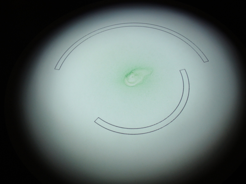
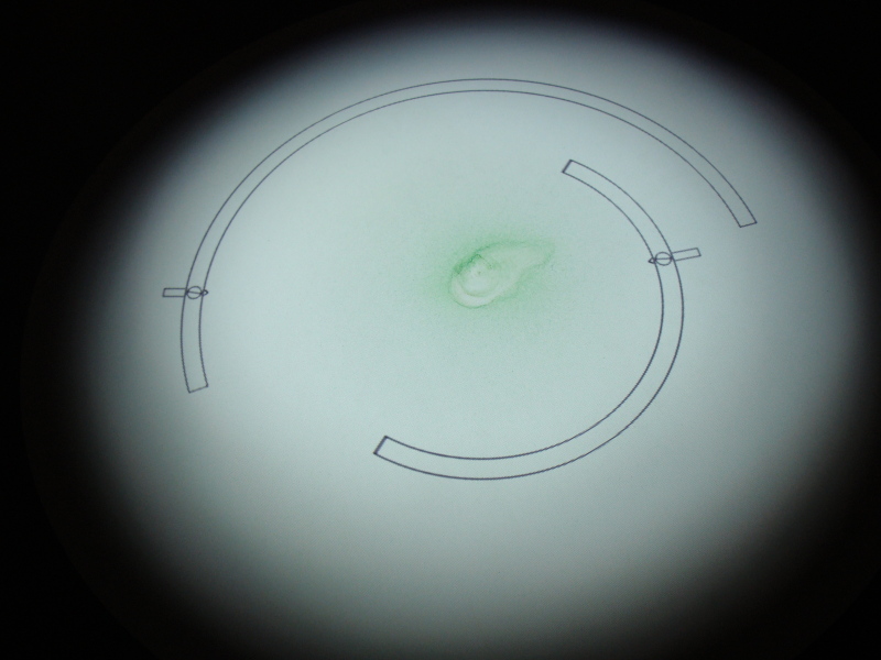
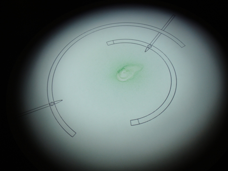
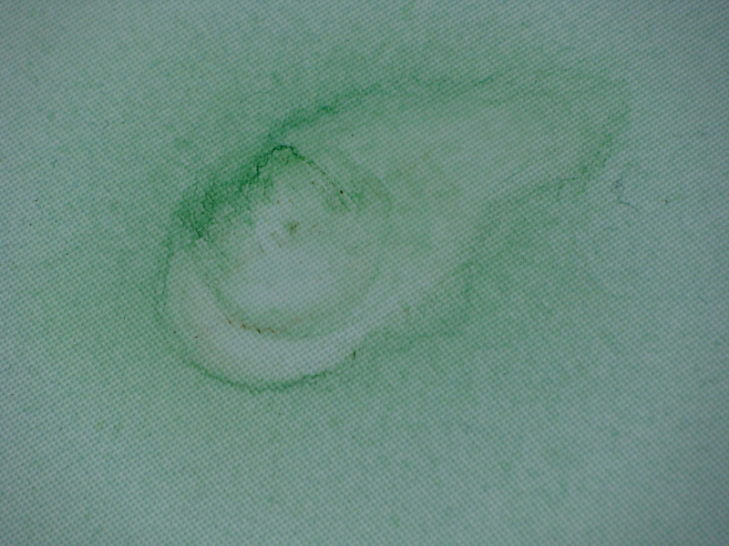
Biopsia This piece consists in a disc where a drop of colored water falls from the ceiling every 2 minutes. An animation of a clockwork mechanism is also projected onto the disc. With these two elements, the water drop and the clockwork mechanism, I tried to address two (seemingly) confronted forces: the irrational (the biological, the fluid, the bodily...) and the rational (the machine, the measurable, the scientifically apprehensible...). The mechanism tries to analyze the accumulating fluid, revolves around it, projects its needles towards the cell-like, liquid stain, that grows and grows as the water keeps falling. But its attempts are futile, for it is only a projected image. The original inspiration for this installation comes from a series of drawings, made in 2004. Go to the drawings section to see them. Pictures (click to enlarge)
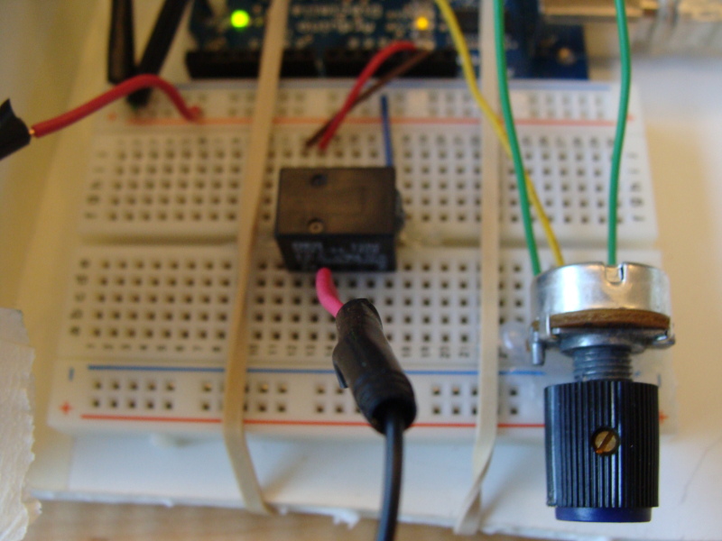
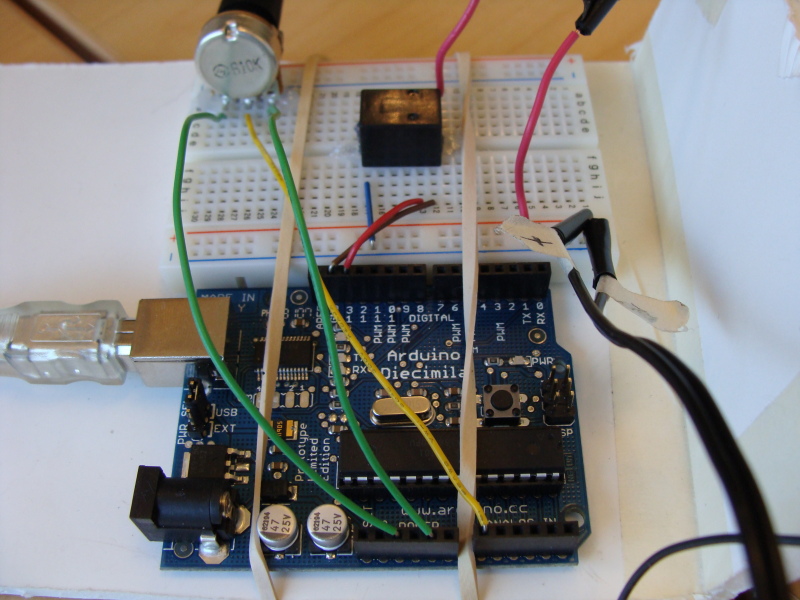
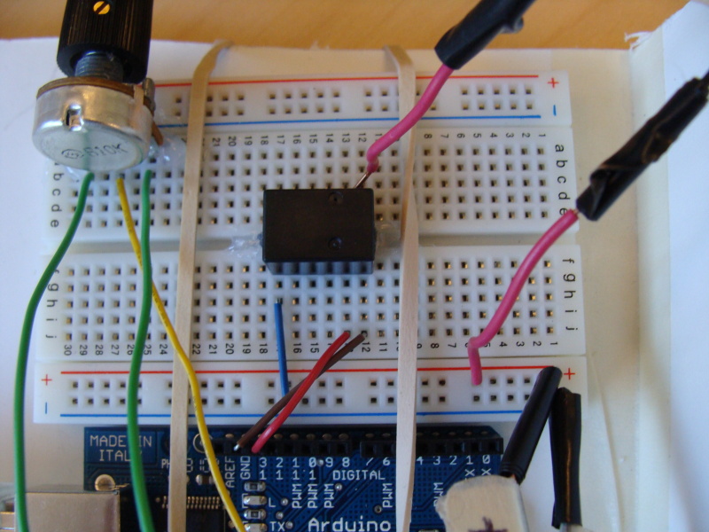
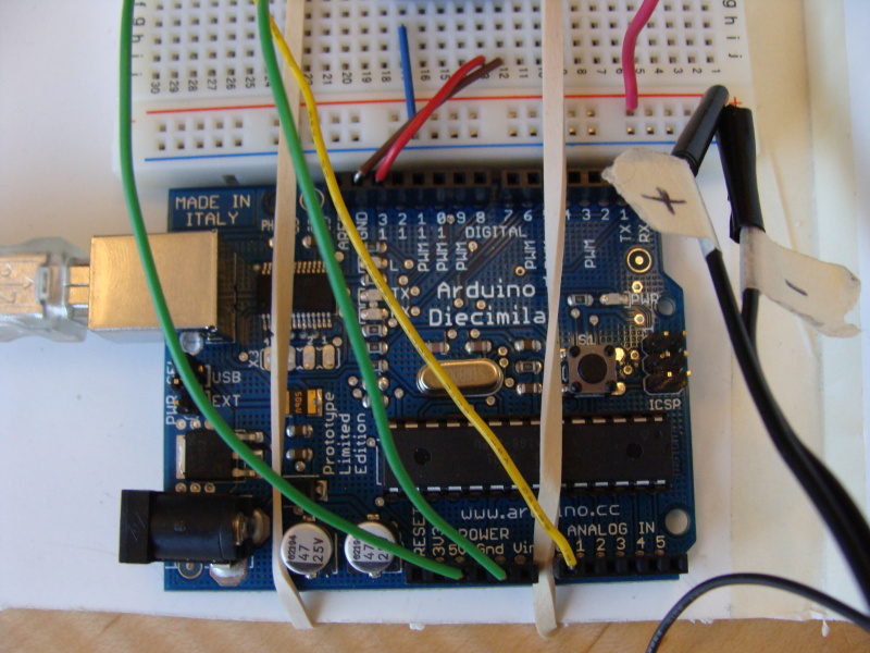
Video (click to download/play) 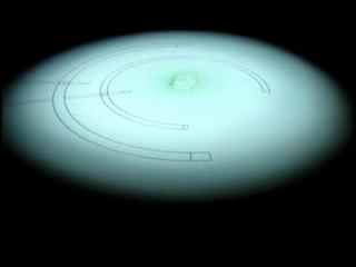 Technical details Biopsia has been implemented with Processing and Arduino. The animation is generated by a processing sketch, that you can get from here. The sketch listens to the serial port, and when the character "1" is received, the animation is restarted. The Arduino board writes "1" to the serial port every 2 minutes, or other user-specified interval. This is also the interval to drip water: the solenoid valve that creates the dripping is switch open through a mechanical relay connected to the digital output of the Arduino board. So in other words, the whole system is controlled by Arduino, since the cycle of the processing animation follows the dripping frequency. The program executed on the Arduino board is available here. In terms of the electronics, the use of the mechanical relay made the circuit very simple, since it is actually the only electronic component (apart of the Arduino board itself and the potentiomenters, which are optional). The relay also allowed to separate the power from Arduino from the power of the solenoid valve. This is very convenient, since otherwise (see here and here), there is the risk of burning the board, if not proper protection is in place (by means of diodes). The Arduino is powered through the USB connection, while the valve is powered by a separate 12VDC, 1A transformer. The relay used is from Radioshack (model 275-240). Schematic of the circuit (click to enlarge): 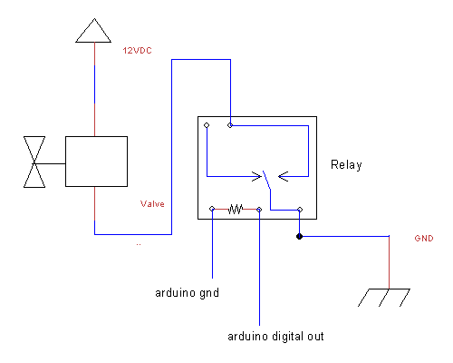 Pictures of the circuit (click to enlarge):
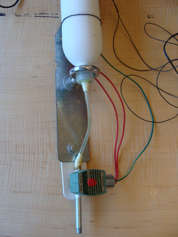
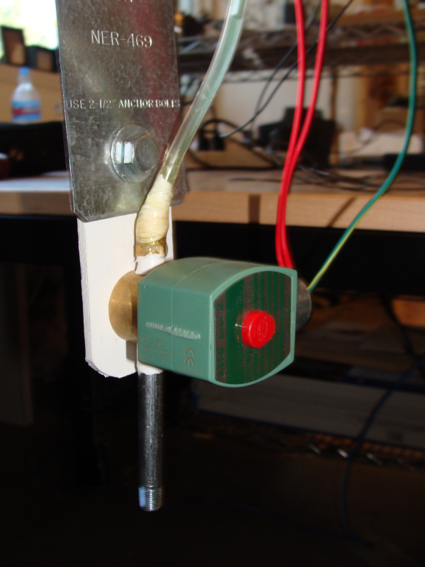
Regarding the solenoid valve, a low pressure, DC model from ASCO was used. The specifications of this model (the ASCO 8262G002) are available here, together with the user and technical manuals. Pictures of the valve and the dripping mechanism (click to enlarge):
Here there are local copies of the manuals of the valve: general specs sheet, installation & mantainance instructions of the solenoid part, installation & mantainance instructions of the valve part. |
|||||||||||
| Andrés Colubri's webpage
:: andres.colubri@gmail.com |
||||||||||||